Gas Scrubber
Gas scrubber are designed to remove contaminants that dissolve in natural gas. Contaminants is contains dirt, condensates, oil and moisture which ensure high degree of purify Natural Gas at Filter Outlet with max flow rate 16920 m3/h at 7 bar.
There are two stages filtration process inside gas scrubber, multycyclone element process and coalesing process which can particulate removal down to 0.01 micron with efficiency 99.97%.
Multicyclone
Multicyclone elements are designed to separate solid and liquid contaminants from gas and have the following advantages :
- Absence of moving parts
- Reliable operation under temperature up to 500 °C
- High efficiency
- Stable pressure drop value
- Simple maintenance
- Wide range of application
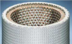
12 Installation of cyclone tubes is fixed between two tube sheets. Gas will enters the cyclone section and then enters each cyclone tube, where fast spinning and result from this centrifugal action moves the liquid droplets and/or solid particles to the bottom of the vessel, and the cleansed gas will streamed to other section of gas scrubber.
Coalesccer
Coalescer are designed for treatment of liquid and gaseous medias and separation of solid and liquid contaminants from the process stream. Separation of liquid contaminants in coalescer is affected due to the ability of filter element to coalesce liquid aerosol particles of fine diameter into larger droplets (0,3 – 0,6 micron) and to drain these droplets into the sump system. The best choice types of coalescing cartridge element from Parker Hanafin that we recommend is 10Q – U51 – 280.
Coalescing cartridges are worked out for liquid and gaseous media processing, where fine treatment is required. Coalescing cartridges will capture particles contaminations from gas and accumulated on filtration material surface. Superfine mist of lubes or moisture, contained in gas, is captured due to movement of the stream around the structural of pore layer. As filtered flow goes thru several layers of filtration material with further increase of pore diameter, mist particles reach droplet size and move inside the layer from inside down under gravitation force. As particles quantity increase, gas permeability of filtration media goes down, thus filter cartridges have to be replaced.
Main Equipments
Multi cyclone filters - coalescers
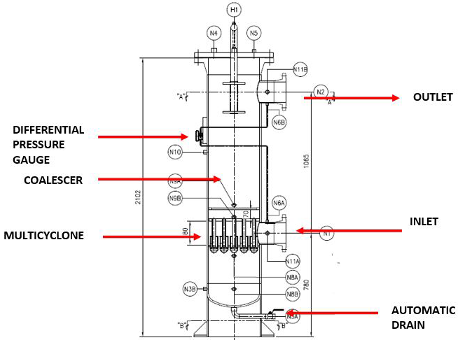
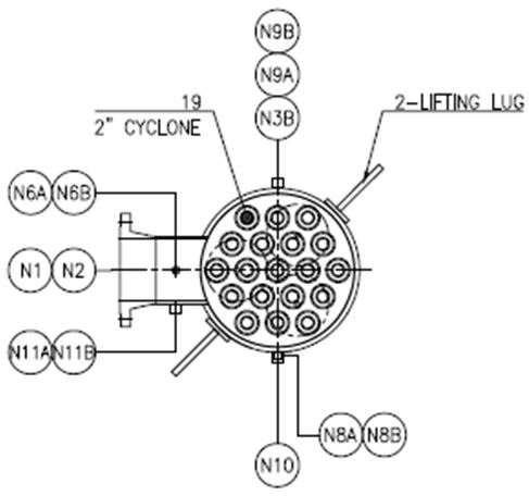
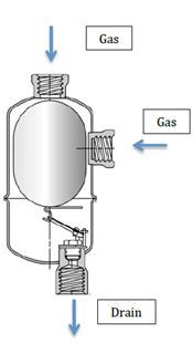
This gas scubber use 2 stages of filtrations, Multi cyclone and coalescing process. Gas will flow through inlet vessel to multi cy clone process to remove liquid contaminants and after multi cyclone process, gas will through coalescer with filter element from parker to remove particle contaminants. There are 19 pcs Multi cyclone and there are parker filter element inside the gas scrubber (see picture Section “A-A”). Tubing is installed at inlet and outlet vessel to give information about the different pressure in inlet and outlet vessel.
Filter Element
There is one best option coalescing element from parker for this Gas scrubber, it is Paker 0Q – U51 – 280, with detail specification below
| Grade | Coalescing,efficiency | Coalescing,filters maximum oil carryover,Ppm,w/w | Pressure Drop (PSID)2 @ Rated Flow |
Micron Rating | |
|---|---|---|---|---|---|
| Media Dry | Media,Wet with 10 wt. Oil | ||||
| 10 | 95% | 0.85 | 0.75 | 2.5 | 1.0 |
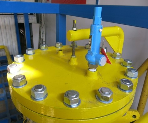
Safety Valve
Relief valves are installed on filter vessels to provide for the bleed-off of excess pressure caused by line surges or thermal expansion. In general, the valves are not designed to handle relief of full flow on a bypass operation, but only to relieve excess pressure. For this Gas Scrubber process using Safety Valve from Niezgodka type 10.1, with detail specification below:
| Model | : | Safety – valve, Spring Loaded |
|---|---|---|
| Temperature Range | : | -10 up to 280 Celcius |
| Pressure Setting | : | 17 Bar |
| Operation Position | : | Vertical |
| Port | : | ½” |
| Material for Inlet + Body |
: | SS430F + Cast Iron |
| Dimensing | : | 50 x 215 mm |
| Weight | : | 1.6 kg |
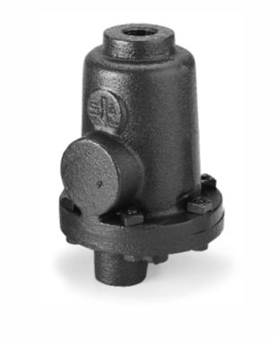
Automatic Drain
Armstrong’s cast iron, free-floating guided level drain traps use the same bodies, caps, level mechanism, valves and seats of Armstrong inverted bucket steam trape that have been proven in years of service. Elliptical floats and high leverage make it posssible to open large orifices to provide adequate capacity for drain trap size and weight. Automatic drainer from Armstrong, mechanical system open and close drainer with small orifice hole good for light liquid – medium condensate capacity. Automatic drain will auto drain every 10 liter.
| Model | : | Automatic float condensate |
|---|---|---|
| Drain performance | : | 1000 Kg/hr at 7 Bar |
| Max Pressure | : | 17 Bar |
| Max Temperature | : | 232 Celcius |
| Operation position | : | Vertical |
| Condensate inlet / outlet |
: | ¾” |
| Orrifice hole | : | Min 5/32” |
| Material for Body & Cap |
: | Cast Iron |
| Material for Valve Seat, Leverage System, Float |
: | Stainless Steel |
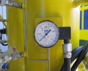
Pressure and Differential Pressure Gauge
The primary reason for installing a differential pressure gauge on a filter vessel is to determine the difference between the pressure in the inlet chamber and the outlet chamber. The resulting number of pounds difference is a direct indication of the condition of the elements contained in the filter vessel. Operation While under pressure, fluid enters the filter vessel through the inlet connection and flows through the elements to the outlet connection. During this filtering process, there is a gradual clogging of the element with solid contaminants. This will result in a gradual increase of pressure and decrease in product flow. The condition of the elements is indicated by the amount of pressure loss shown on the gauge. If the differential pressure reach the allowable maximum limit, filter element should be replaced immediately.
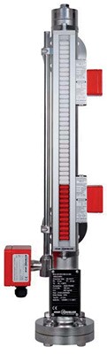
Level Gauge
The bypass level indicator model BNA consists of a bypass chamber, which, as a communicating tube, is connected laterally to a vessel via at least 2 process connections (flanged, threaded or welded). Through this type of arrangement, the level in the bypass chamber corresponds to the level in the vessel. The float with a built-in permanent magnetic system, which is mounted within the bypass chamber, transmits the liquid level, contact-free, to the magnetic display mounted to the outside of the bypass chamber. In this are fitted, at 10 mm intervals, two-coloured plastic rollers or stainless steel flaps with bar magnets.
Through the magnetic field of the permanent magnetic system in the float, the display elements, through the wall of the bypass chamber, are turned through 180°. For an increasing level from white to red; for a falling level from red to white.